|
|
Volume 4 No.2, Spring 2001 |
ISSN# 1523-9926 |
|
|
Volume 4 No.2, Spring 2001 |
ISSN# 1523-9926 |
Daniel Chen
chen@iet.cmich.edu
Central Michigan University
ABSTRACT
This paper describes the use of a CAD system with a constraint-based design tool to analyze planar mechanisms. The techniques have been developed for velocity and acceleration analysis based on the polygon method. The system of constraints provided by the software are used to impose relations between the vector polygons and the skeleton form of a mechanism. In addition, the equations are also used as constraints to impose the mathematical relations between the velocities and accelerations. The techniques developed in this study are proved to be much more effective and accurate than the traditional standard graphical approach that requires drafting.INTRODUCTION
The complexity of the mathematics associated with vector addition has, for decades, resulted in the preferential us of the graphical approach for the analysis of velocity and acceleration of a planar mechanism. [1]. However, the graphical approach requires manual construction of vector polygons using velocity and acceleration components. This time-consuming yet less accurate process must be repeated for a large number of positions because it is necessary to investigate the full range of motion to determine the extreme conditions throughout a cycle [2]. As low-cost, high-speed computing becomes readily available, 3D CAD software packages are becoming an integrated part of engineering programs. These software packages with constraint-based features are able to perform solid modeling and analysis based on solid model data [3]. With such a design tool, the velocity and acceleration polygons can be quickly and accurately constructed and related to a planar mechanism using proper constraints provided by the software.
The constraints utilized in this study can be divided into three categories. They are geometric, dimensional and algebraic constraints. The geometric constraints include those of parallelism, perpendicularity, coincidence, and location in space. The dimensional constraints include both linear and angular dimensions. The algebraic constraints use equations to relate one dimension to the other. One of the applied dimensional constraints can be set as the controlled factor to animate the mechanism using the dimension animation function provided by the software [4]. Since the associated velocity polygon is constrained to the mechanism, it can also be animated. Thus, the change of velocity through its range of motion can be quickly and easily observed. The purpose of this study is to develop a constraint-based technique for velocity and acceleration analysis. All the analysis in this study was completed utilizing I-DEAS on the Unix-based Sun workstation. However, the analysis can be as effective and efficient using any CAD software such as Mechanical Desktop, Pro-Engineer or SolidWorks, as long as the selected CAD software is constraint-based.
VELOCITY ANALYSIS
A standard four-bar mechanism in skeleton form as illustrated in Figure 1a is used to demonstrate how the velocity analysis is carried out using I-DEAS. The mechanism consists of a crank, a connector and an oscillating arm. They are first drawn as straight lines with linear dimensions of 20, 100 and 80 millimeters respectively. The dimensional constraints also include the horizontal and vertical distances (65 and 8 millimeters) used to relate the location of the grounded fixed pivots of the crank and oscillating arm.
Figure 1. Constructed Velocity Polygon
Figure 1b illustrates the constructed velocity polygon based on this mechanism and the assumption that the linear velocity at the moving end of the 20 millimeter crank is 60 millimeters per second. The linear dimension of 60 millimeters is based on a scale of 1 millimeter = 1 millimeter per second applied to a line that represents the given linear velocity at the end of the crank. Because velocity must be maintained at a right angle to the crank, the geometric constraint of perpendicularity must be applied between the crank and the velocity vector. The velocity polygon is then completed with the next two vector components – the relative velocity, which is perpendicular to the connecting rod, and the velocity at the end of oscillating arm (in dotted line), which is perpendicular to the oscillating arm. These two linear velocities can be quickly determined using either the measurement or dimensioning command on the CAD system.
One of the major advantages of using a constraint-based design tool for velocity analysis is that the modification of a velocity polygon can be easily achieved using the CAD command of “drag". This is possible because the velocity polygon is forced to change with the mechanism due to the applied geometric constraints. Figure 2 depicts such an example. In this figure, both the relative velocity and the velocity at the end of the oscillating arm are quickly obtained while the crank is dragged to a new position (110 degrees counter-clockwise from its initial position).
Figure 2. Velocity Polygon with Applied Constraints
A more complete velocity analysis may be carried out using the CAD command of “dimension animation". This function is originally designed to animate planar mechanisms in skeleton form. This very same function can also be used to animate a velocity polygon, if the polygon is properly constrained to the mechanism. Figure 3 depicts such an example. With an angular dimension (120 degrees) between the crank and horizontal ground as the controlled parameter, the crank will rotate completely around the fixed pivot. However, the range must be set between 0 to 360 within the “dimension animation" CAD command. Other entries needed include the speed and number of cycles to complete the animation. The same figure illustrates how the velocity polygon is animated. It shows how both the relative velocity and the velocity of the end point of the oscillating arm vary as the crank rotates 30 degrees at a time.
Figure 3. Vector Polygon with Dimension Animation
ACCELERATION ANALYSIS
A similar approach can be followed when dealing with acceleration analysis using a constraint-based design tool. However, the acceleration polygon is required in addition to the velocity polygon as illustrated in Figure 4.The components involved in the construction of the acceleration polygon include: the normal component of acceleration at the end of the crank (180) which must be placed parallel to the crank; the normal and tangential components of relative acceleration (33 and unknown) which must be placed parallel and perpendicular to the connecting rod, respectively; the normal and tangential components acceleration at the end of the oscillating arm (92 and unknown) which must be placed parallel and perpendicular to the oscillating arm, respectively. The tangential component of acceleration at the end of the crank is zero, because the crank has a constant angular velocity. All the normal components are calculated with velocity square over the length of the link. All the accelerations are in millimeters per second per second.
Figure 4. Acceleration Polygon
The equations can be incorporated in the CAD command of “part equation” to
create an algebraic constraint that is ideal for relating one dimension to the
other. Figure 5 depicts how the part equations are used to relate the dimension
of the normal component of relative acceleration (RA) to relative velocity (RV),
and the normal component of the acceleration (A) to the velocity (V) at the end
of the oscillating arm. The name, expression and value in the lower window are
entered automatically as soon as the dimensioning takes place. Both RA and A are
switched from a status of “constant” to “from equation”, so they can be treated
as the dependents of RV and V, respectively. This also explains why both RV (58
millimeters per second) and V (74) need to be dimensioned in the velocity
polygon before A and RA can be calculated using the part equations.
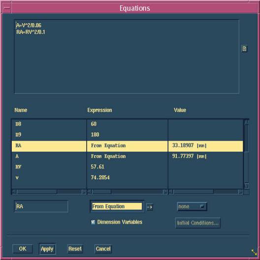
Figure 5. Part Equations
Figure 6. Modified Acceleration Polygon
CONCLUSION
Constraint-based design tools have been developed for applications in solid modeling. They have been proven to be useful in velocity and acceleration analysis in this study. The use of a constraint-based design tool, saves a tremendous amount of time by eliminating the laborious manual construction required for the traditional approach. A possible further application of constraint-based design tools in kinematics and mechanism design could be the synthesis of linkages.
REFERENCES