|
|
Volume 3 No.3, Fall 1999 |
ISSN# 1523-9926 |
|
|
Volume 3 No.3, Fall 1999 |
ISSN# 1523-9926 |
Eric Tisdale
etisdale@gw.bsu.edu
Ball State University
Muncie, Indiana 47306
ABSTRCT
Capstone courses provide students with an opportunity to synthesize concepts previously learned in their curriculum, while applying critical thinking and troubleshooting skills. However, due to the consecutive layering of prerequisite knowledge required for design theory, there are often key higher order skills or concepts that are glossed over, or omitted from supporting courses, due to time constraints at the end of a term. This paper focuses on the three areas that most often create a barrier for students in successfully completing the Senior Project Manufacturing - Automation Capstone Course. The major problems identified are all electrical / electronic in nature and include: 1) Power loading. 2) Signal level changes. 3) Connector pinouts. Electrical power loading has to do with understanding the power requirements for devices used in a system. Signal level changes refer to electrical signal levels and cover both AC and DC changes as well as voltage magnitude changes. Being able to read connector pinouts from the data sheet or maintenance manual will allow the student to configure the system. Specifics of these problems will be discussed and suggestions presented.
INTRODUCTION
The Capstone course serves as a culmination of work done in a college degree program and is typically project oriented[1]. Projects vary between student teams. Therefore, the course structure must be flexible and responsive to the unique set of problems and challenges for each project. The Capstone course is typically taught without a textbook[2], particularly as one book could not cover all of the necessary information. Higher education serves to teach students how to learn. The capstone course requires an understanding of how to identify a problem, determine potential causes, and utilize available resources in narrowing down a solution. Therefore, preparation for this course should include all things known and all things thought of[3]. Unfortunately, it is impossible, if not impractical, to identify even half of what the new college graduate will need to know. Programs typically present materials in the general case and plan to have the student update specifics as they are challenged in the field.
An application-oriented program has a unique set of problems. Details that are needed to make an operational system must be covered along with the system theory. Those specifics that are sometimes missed, or not understood by students because they are not necessarily identified as course objectives, are typically taught to industrial technology students and not to engineering students. The applications-oriented program must bridge both sets of knowledge. Theory courses are taught with the intent to cover specific identified objectives. The details and important knowledge that could be expanded from these are not always stressed with the student, and the student often ignores the items that look like add-ons rather than course objectives. Power loading, level conversions, and connector pinouts are usually side notes to another major objective. Electrical power is not usually discussed in design until after the first design pass. Power discussions require that something is known about the current levels present before heat can be discussed. In a design situation, the current levels won’t be known until after the initial design is complete. Because the applications course requires construction, details that come at the end of theoretical design discussions and might be ignored, are required[4] and must be completed.
THE PROBLEM
The Capstone course at Ball State University simulates a manufacturing plant with emphasis placed on assembly flow, cost control, and quality control. The students have had courses that should allow them to set up and operate a plant with the proper flexible manufacturing techniques currently used in industry. While the course is about manufacturing, the problems that cause the greatest concern are related primarily to the Input / Output (I/O) relationship between interfaced components.
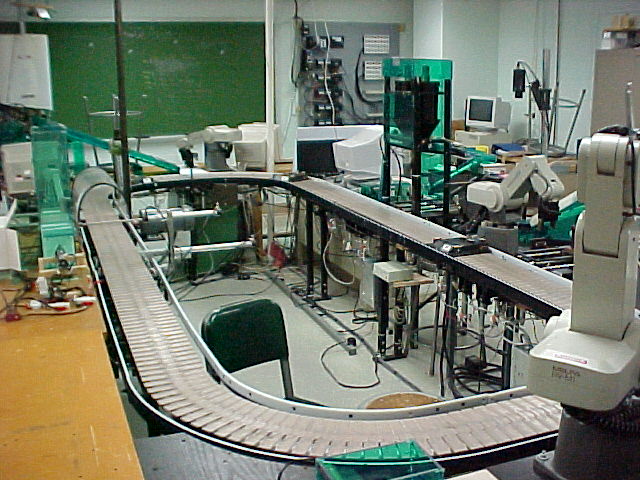
Figure 1: CIM Lab, Plant Simulation
Other than robots, there are no systems of commercial automated machinery on the Ball State capstone assembly line (see figure 1). All processing and assembly systems have been constructed by the students. There is no machine that cuts parts out of plastic, wax, or metal at the push of a button. On the Ball State assembly line, the student must build and automate any process used. The basic concept is to use online and offline modules to simulate the assembly of a complex device. This is accomplished by using colored cups with colored marbles on a multi-hole wooden base with added pen or clip holders to simulate a product (see figure 2). Possible permutations are greater than typical assembled products. One of three cup designs is filled with up to twelve marbles from two color feeders and positioned on one of two bases with one or two of three different clip devices. This provides a significant number of assembly combinations. The student is asked to provide automation for part of an assembly process. The instruction is brief and allows the student complete control of his part of the process. Students typically review what was done in previous years and add their own input for the parts that were not done or not done correctly last year.
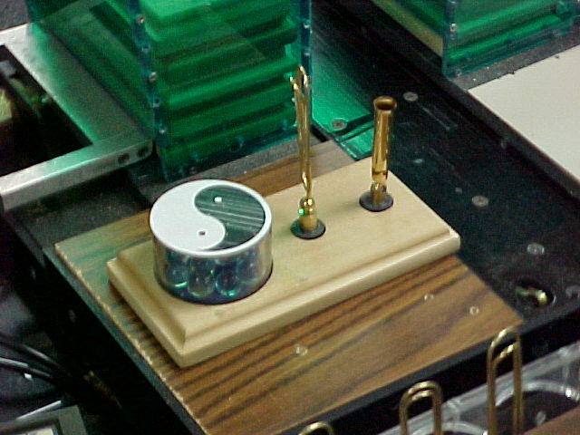
Figure 2: Simulated Product
History has shown that electrical connection of devices, pin connections, loading, and power requirements are major difficulties in such a course. Although the student may understand the basic design theory, the inability to execute the details of its implementation will prevent success. The goal then would be to prepare the student for specific applied problems in courses leading to the capstone. While these items are not what would be considered course objectives in any course, they could be grouped with the discussion of industrial electronics, control systems, digital electronics or interfacing systems.
This paper will focus on the three major pitfalls found in our Capstone preparation. They are: 1) Electrical power requirements, specifications, and loading. 2) Electrical signal level changes. 3) Signal connector pinouts. These items are now specifically covered in the Digital Electronics course which has been expanded to cover Industrial Controls. The course text[5] covers sensors as an input and discusses how these signals are used. Afterwards, control aspects are introduced. Throughout the course, discussions of power, loading, specifications, and documentation are presented.
Power required is a data sheet problem. The student must find a specification sheet to understand the requirements. Level changes are either power type levels or amplitude levels. Relays and op-amps can solve these problems. Connector pin-out is an understanding of how data is presented. The specification sheet has the necessary data. The student must understand the information presented.
POWER
One of the systems used on the Ball State system to control motors and pneumatic valves is made by a company called A-Bus Systems. They insert cards into a personal computer to make a control system. The control aspect requires a circuit card that will take external signals in while electrically isolating one system from another. The other part of the control aspect is the need to send out a signal to a controlled device. The device being controlled will have requirements on the amount of voltage or current necessary to move the mechanism. The control board will also have limits in what it was designed to provide in the way of voltage or current for the control process.
The IN-141 is an isolated digital input card. That means that the input is protected from whatever signal source generates the signals and that the signal being received is an "on or off "(digital). The ST-143 is an output board capable of switching eight loads of up to 250mA each. That means that the board can turn a device "on and off" upon command as long as the device is drawing no more than 250mA of current while operating. Both of these boards are mounted on an extended ribbon cable that attaches to an AR-133 within the computer. The interface inside the computer only provides a way for the computer to talk to the control boards. The computer must be programmed to make the decisions.
An intermittent problem with an IN-141 was identified. The board had a high failure rate and was inconsistent in its operation. Since this unit was put into service by a previous class, the data sheets were not available when the problem surfaced.
Analysis of the problem showed that power to the IN-141 was being provided by a 12V DC - 50mA AC adapter. The student assumed that 12V DC was what was required and didn’t read the part that said 8V to 12V DC @ 100mA. The minimum and maximum input signal is rated at 5V to 35Vwith a minimum current for an accurate reading of 5mA to the board.
After looking at the specifications, it was determined that the input signal was able to provide the necessary 5mA to the board but the power supply provided only 50mA and the board needed 100mA to operate. After replacing the power supply with one rated at 300mA, there were no more problems with the board.
Another part of that same station uses an output board (ST-143) that is rated for switching 250mA on each of eight lines. This device has not been questioned and is currently in operation. There is a comment in the student recommendations concerning reliability. The suggestion is to replace the I/O cards with a programmable logic controller (PLC). The PLC recommended will switch 2A loads. If we look at the solenoid coil that is being controlled, the label indicates 12V DC @ 5.4W. The computed current from that load is 450mA. Failures would be expected in this system since a device rated for 250mA is being utilized to switch 450mA loads. Although student documentation was used to find the data, students have not found this discrepancy to date.
SIGNAL LEVEL CHANGES
Another typical assembly line device is a relay box (see figure 3). The box is used to connect the trigger signal from a 120V AC programmable logic controller (PLC) to the "device ready" input signal on a 5V DC robot controller. The PLC runs from the main system control program and takes signals from the conveyor line which uses 120V AC power. Mechanical switches on the conveyor line indicate the presence of pallets as assemblies move down the conveyor. When a pallet arrives at a workstation, the PLC is triggered by the roller switch located at the station. The PLC program then directs the robot to move into position to load a cup on the pallet.
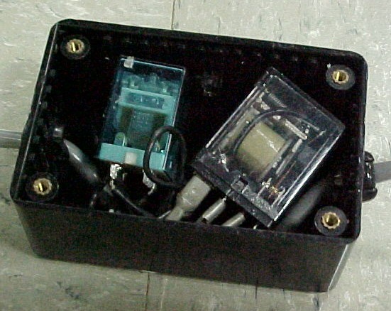
Figure 3: Relays in a Box
The robot is a Movemaster EX from Mitsubishi. This is a general purpose commercial robot used in industrial applications. The Movemaster operates in the full automatic mode by running an internal program that waits on a signal from an external interface connection. The external I/O connection is rated at 12 to 24V DC. "On" is set for over 9V and "off" is below 2V. When the Allen Bradley PLC sends a signal, it is at 120V and it is AC.
An AC (alternating current) signal cannot pass data to a DC (direct current) system without some intervention. The signal levels involved are also a problem. The 120V signal will damage a system if sent to a board expecting a maximum of 24V. The relay box separates the two power systems so that the signal amplitude does not cross to the robot and so that the data in the PLC signal passes to the robot’s board.
After the assembly line process and expected voltage levels are discussed, the student is asked to come up with solutions to the communications problem. They will realize that the PLC cannot feed directly to the robot. Usually there is a blank expression concerning what hardware would allow them to make those changes. Students do not readily understand the problem until they look at the relay box wiring so they are asked to diagram the connections going in and out of the relay box and to explain its purpose. The students will need examples of both mechanical and solid state relays along with the data sheets on them.
Mechanical coils have a very broad range of operating conditions while solid state relays have a narrow range and are harder to visualize in operation. It is instructional to have the student experiment with the relays in the lab to see what level of voltage & current will activate the coil or switch the relay.
Students at this beginning electronics level (sophomores & juniors) will stop when instructed to "look at the relay box and diagram it." For one thing, it is in the system and part of the conveyor line. Secondly, it is enclosed in a box with a screw-down lid. The student must be told to open the box and look inside, or they would submit the diagram of wires going in and out of the box with no information about what is in the box. Since the student was not part of the construction of the conveyor line, it is expected that they would not want to break it. The student needs to realize that it is mandatory that complete systems are diagramed in order to diagnose problems. Partial information is useless.
Inside the box are two relays. One is designed to take 120V as an activating input. The other is designed to take 24V to activate the coil. For this exercise, it is suggested that an instructor actually build a relay box with two sets of input wires and two sets of output wires enclosed in a bud box. If something in the project lab would use a similar device, copy that. If not, a 120V signal to light a 3V flashlight bulb and a 5V signal to light a 120V bulb may be used. Students need to see and understand the reasons to pick one relay over another and to see how they are connected. The current levels needed to trigger a solid state relay are better defined than the half of specified level on the mechanicals but the mechanicals have a very broad range and have multiple contacts available with only one activating signal. Local parts catalogs can be used when describing relays.
SIGNAL CONNECTOR PINOUTS
The next major problem that the students have is how the relay box connects to the robot. The input to most devices is electrically isolated at a connector. The Movemaster uses a special 50 pin connector for external inputs. It is optically isolated and needs external power. The connecter includes all of the data lines that are necessary to allow another device to activate a relay in the robot or to check the condition of the robot’s controls. The wiring of the connector is usually something the students understand. The nomenclature is another thing all together.
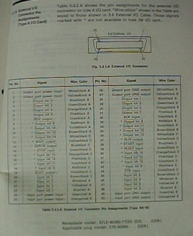
Figure 4: Movemaster 50 Pin External Input Connector
On a pin-out diagram (see figure 4), the numbered lines are connector pin numbers and will be labeled with the signal that goes to that pin. If the name has a bar or line above the name of the signal, it means that the active signal condition is a "not" value. "Not" means that a low level signal will cause a change. The activation is accomplished by tying the pin to ground. If the robot is to receive an input to make it work and the input pin line signal description has a bar over it, the incoming signal must drop from the high condition to the low condition. The high to low change is what the robot interprets as a start command. Understanding what the activating signal change must be is necessary for operation. The student would never be able to guess what the activation state is. It must be discovered from the documentation.
On the Movemaster, there are two kinds of I/O boards. The "A" unit uses high signals as active and the "B" unit uses low signals. The student needs to open the robot control box and find out which board is installed or communication will never be accomplished. The low active state is common in the industrial world. It is cleaner to hold a high state and ground the signal to bring it low than it is to take a chance that something is wrong with the wire and the signal level cannot be raised to the high active condition because of line problems. It is easier to check the line if the normal is high and the activation signal is a low.
CONCLUSIONS
An application-oriented program has its own set of problems. If theory was the major concern, the student would never have to build anything. Since the Manufacturing Engineering Technologist degree is an application-oriented program, construction must occur and therefore, the details of design and implementation must be covered. The MET program includes all of the basics necessary for a good design or exposes the student to enough information that successful design is possible. The goal now would be to insure that the detail of electrical power loading, electrical signal levels, and electrical connector notation are covered with emphasis placed on system connectivity.
BIBLIOGRAPHY
| [1] | Michalson, Labrnte, Capstone Design in the ECE Curriculum: Assessing the Quality of Undergraduate Projects at WPI, American Society of Engineering Educators Annual Conference, 1998. |
| [2] | Latino, Hagan, A Unique Capstone Design Program, American Society of Engineering Educators Annual Conference, 1996. |
| [3] | Fahlsing, A Capstone Laboratory for an Introductory Electronic Devices and Applications Course, American Society of Engineering Educators Annual Conference, 1998. |
| [4] | Deleveaux, Ruud, Designing and Teaching a Successful Industry Based Capstone Design Course, American Society of Engineering Educators Annual Conference, 1997. |
| [5] | Johnson, Curtis, Process Control Instrumentation Technology 6th Edition, Prentice-Hall, 2000. |