|
|
Volume 3 No.2, Spring 1999 |
ISSN# 1523-9926 |
|
|
Volume 3 No.2, Spring 1999 |
ISSN# 1523-9926 |
Hydraulic Jack Laboratory Experiment
Mechanical Advantage and Efficiency
Paul H. Ricketts
ricketts@nmsu.edu
Department of Engineering Technology
New Mexico State University
Las Cruces, New Mexico
Abstract
This paper describes an experimental laboratory procedure for determining the mechanical advantage and efficiency of a small hydraulic jack. The testing procedure and required calculations demonstrate how the efficiency of a simple machine can be determined, and how multiple mechanical advantages in a simple machine have a multiplying effect, rather than an adding effect. The cost to set up the experiment is relatively low and the testing procedure is straightforward, yet very informative for the students.
Introduction
Hydraulic jacks provide a means of lifting loads that otherwise could not be lifted by conventional mechanical (screw and scissors) jacks. A common hydraulic jack with a lever arm and pump has two Mechanical Advantages (MA) built into it. One MA is due to the lever arm and the other is due to the ratio of the ram piston diameter squared (D2) to the pump piston diameter squared (d2), D2 / d2. The two MA’s combine in a manner that results in a multiplying effect rather than an adding effect, which yields a much larger overall MA. The efficiency of a jack can be determined from the basic definition of efficiency, which is output / input. This laboratory exercise is appropriate for mechanical engineering technology or mechanical engineering students for a course in applied fluid mechanics, fluid power or machine design. The needed equipment is readily available off-the-shelf, at a very low cost.
Background
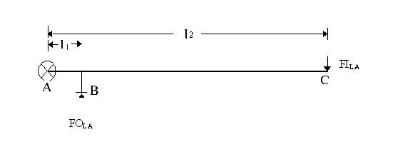
A hydraulic jack has a relatively large overall MA due to the lever arm and the ratio of the ram piston diameter squared to the pump piston diameter squared. The MA due to the lever arm can be demonstrated and determined by analyzing the simple lever arm shown in Figure 1. Point A is the lever arm pivot point, Point B is where the lever arm applies an output force (FOLA = force out, lever arm) to the jack’s pump and Point C is where the input force (FILA = force in, lever arm) to the system is applied, usually by hand.

Figure 1. Hydraulic jack lever arm.
Summing moments about Point A yields;
S MA = 0 = (FOLA * l1) – (FILA * l2)
or
(FOLA * l1) = (FILA * l2)
or
FOLA / FILA = l2 / l1.
The mechanical advantage due to the lever arm is either of the above ratios, or
MAlever arm = FOLA / FILA = l2 / l1. Equation (1)
It is usually difficult to determine FOLA, but easy to measure l1 and l2, and therefore possible to calculate MAlever arm.
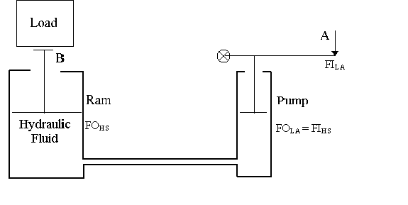
The mechanical advantage due to the ratio of the ram diameter squared to the pump diameter squared can be developed by analyzing the basic fluid principles of the jack. A simplified hydraulic jack is shown in Figure 2.
Point A is where the force into the system is applied (FILA) and Point B is where the force out of the system (FOHS = force out, hydraulic system) is used to lift a load. In the case of a jack the force out of the lever arm (FOLA) is equal to the force into the hydraulic system (FIHS) at the pump.
The definition of fluid pressure is a force per unit area, or in equation form,
P = F / A Equation (2)
where P = pressure (N/m2, psi),
F = force (N, lbf), and
A = area (m2, in2).

Figure 2. Simple hydraulic jack system.
The pressure throughout the hydraulic fluid is assumed to be constant, and for Figure 2 the following applies,
P = FOHS / AD = FIHS / Ad
where P = the pressure of the hydraulic fluid in the jack (N/m2, psi)
AD = the area of the ram piston (m2, in2) and
Ad = the area of the pump piston (m2, in2).
Rearranging the above yields
FOHS / FIHS = AD / Ad = (p D2/4) / (p d2/4) = D2 / d2.
The mechanical advantage of the hydraulic system is any of the above ratios, or
MAhydraulic system = FOHS / FIHS = AD / Ad = D2 / d2. Equation (3)
Measuring the piston diameters is usually easier than measuring the forces into and out of the hydraulic system.
When students are posed the question "How do you determine the total mechanical advantage in a system with multiple MAs?", most will reply with "You add them." This, however, is not true. One way to determine how to deal with multiple MAs is to think of them as being in series inside of a machine. For example, the following block diagram, Figure 3, demonstrates how two MAs, MA1 and MA2, can be manipulated to determine the overall MAtotal.

Figure 3. One system with two mechanical advantages, MAtotal = Out / In = 30 / 5 = 2 * 3 = 6.
Figure 3 shows that the total system MA is determined by taking the ratio of the output to the input, or by multiplying the individual MAs. For the topic at hand, the total mechanical advantage of the hydraulic jack would be determined by multiplying the MA of the lever arm by the MA of the hydraulic system, or
MAtotal = MAlever arm * MAhydraulic system .
The efficiency of the hydraulic jack can now be determined from the following,
h = (Output / Input) * 100 = (Output Force / (Input Force * MAtotal)) * 100
= (FOHS / (FILA * MAtotal)) * 100 Equation (4)
where h = the jack efficiency (%).
Equipment
The following is a list of equipment required to perform the experiment.
1. Small 1 or 2 ton hydraulic jack
2. Assortment of small weights
3. Assortment of large weights
4. Weight hanger
5. Load Cell
6. Scale
7. Testing apparatus
The testing apparatus can be constructed out of readily available materials. A testing apparatus that could be used is shown in Figure 4.

Figure 4. Testing apparatus example.
Experimental Procedure
Student’s Laboratory Report
As a minimum the students should include the following in their report of the results.
References
Biography
Paul Ricketts is an Associate Professor of Engineering Technology at New Mexico State University (NMSU). He has 5 years of industrial experience with an electric utility, and has taught in engineering technology for 11 years. He has a BS in Engineering Technology from NMSU and a MS in Mechanical Engineering from the University of Texas at El Paso. He is active in the American Society of Mechanical Engineers (ASME) and the American Society for Engineering Education (ASEE).