This paper describes a laboratory experiment for illustrating basic Strength of Materials concepts. This experiment was introduced in the Mechanical Engineering Technology Applied Strength of Materials course at Purdue University. The experiment illu strates combined normal stress due to bending and axial loading. This is an excellent tool for communicating basic Mechanics of Materials concepts while also stimulating interest and visual understanding. The experiment was developed for undergraduate e ngineering technology students but it is equally valuable for engineering students.
The purpose of this experiment is to illustrate the basic strength of materials concepts, specifically combined (i.e. superimposed) axial and flexural normal stresses. This combined normal stress experiment uses a custom built C-clamp to illustrate co mbined axial normal stress and bending normal stress in a T-shaped cross section. The first step in the experiment is to gather strain data at the tension and compression sides of the clamp-body as the clamping force is increased. The next step is to me asure cross-sectional dimensions and calculate the centroid location and moment of inertia. Then using Hooke’s Law, the flexure formula, and the axial stress equations, plus the experimental strain data and area properties, the students are systematicall y led through a process to find the clamping force. All the information necessary for replicating this experiment is provided in this paper--including descriptive diagrams and step-by-step instructions.
The following equipment and supplies are needed to perform this experiment:

Figure 1. The C-clamp.

Figure 2. The C-clamp cross-section at line AA.
The following section is an outline of the experimental procedure.
The following outline provides a step-by-step procedure for analyzing the data and ultimately determining the incremental clamping forces. A review of the basic strength of materials principles is included.

Figure 3. Cross-sectional dimensions.
| (1) |
| (2) |
where:

Figure 4. Free Body Diagram of the C-clamp.
The variables are defined as follows:
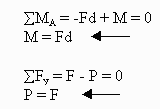
Performing a static force analysis on the FBD gives the following:
 |
| (3) |
where:
| (4) |
where:
 | (5) |
where:
The stress on the compression side of the clamp is:
 | (6) |
where:
 | and |  | (7) |
where:
Both cT and cC are shown in Attachment I.
 | and |  | (8) |
where:
 | and |  | (9) |
where:
From equations (9) determine the clamping forces using the tensile strain values and record these on the data sheet. Then calculate the clamping forces again using the compressive strain values. The clamping force values should be approximately equal using both methods.
The calculated clamping forces are very accurate using the procedure described in this paper. The experimental tensile and compressive strains produce calculated clamping forces that differ by only ± 2% from 0-2 turns. By using a load cell, it was determined that the clamping force at 2 turns is approximately 125 lbs. It was also determined that the experimentally calculated forces differ from the actual forces by only ± 2% from 0-2 turns.
This experiment is very effective in communicating basic strength of materials concepts and stimulating student interest. It also produces excellent results with minimal error. This experiment can be easily added into an existing laboratory course wi thout much expense or preparation. Also, the complete experimental procedure and data analysis is short enough that it can be performed during a two-hour time period.
Michael Magill is an Associate Professor in Mechanical Engineering Technology at Purdue University. Prior to 1995 he was on the Engineering Technology faculty at Oklahoma State University for eleven years. In the summers he works as a structural insp ector on major construction projects. He received his B.S. and M.S. degrees in Mechanical Engineering and his Ph.D. in Civil Engineering--all from Oklahoma State University. He is a member of the American Society of Mechanical Engineers (ASME), American Society of Civil Engineers (ASCE), and American Society of Engineering Educators (ASEE).
Attachment I
COMBINED STRESS DATA SHEET
Name: ___________________________________________ Date: _______________
Division: _______ Section: _________ Group: _________ Clamp #: ____________
|
Number of Turns |
Tensile Strain (m e ) |
Calculated Clamping Force (lb) (Using tensile strain) |
Compressive Strain (m e ) |
Calculated Clamping Force (lb) (Using compressive strain) |
|
¼ |
||||
|
½ |
||||
|
¾ |
||||
|
1 |
||||
|
1 ¼ |
||||
|
1 ½ |
||||
|
1 ¾ |
||||
|
2 |
