|
|
Volume 5 No.1, Winter 2003 |
ISSN# 1523-9926 |
|
|
Volume 5 No.1, Winter 2003 |
ISSN# 1523-9926 |
| Nancy L. Denton | Kevin Knight | |
| nldenton@tech.purdue.edu | kevinyte@hotmail.com | |
| Purdue University | Purdue University |
Purdue University’s Mechanical Engineering Technology (MET) Department has offered a junior/senior level elective course in machine diagnostics for the past decade. MET 317 Machine Diagnostics is an upper division elective course designed to familiarize students with predictive and preventive maintenance concepts and practices. Background topics include single degree of freedom vibration theory, basic signal processing, and an overview of maintenance philosophies. Students are introduced to root cause determination based on machinery operating parameters such as lubricant contamination level, infrared thermography, and especially vibration analysis. A key course requirement is the definition and completion of an open-ended group project that applies and extends course topics. The projects tend to be as diverse as the students’ interests, with recent examples ranging from a comparison and analysis of vacuum pump system vibration characteristics to a study of speaker filter performance. Identification of projects that will benefit a business or facility is encouraged.
The project described here was developed and completed by students Kevin Knight, Jon Weiss, Jeremy Wenzel, and Jim Prough during the Fall 2000 semester. Through summer internship experience, Kevin was aware that owners of a late model sport utility vehicle have been returning their vehicles to the dealers complaining of a “whining” noise coming from the rear of the vehicle. The noise occurs only when cruising at approximately 55-60 MPH. The automotive company determined the noise emission comes from the rear axle on its two-wheel drive models and from both front and rear axles on the four-wheel drive models. Engineers from the axle manufacturer and automotive company worked together for two years to develop a solution to the whine problem. Failure to resolve this design problem subsequently resulted in the axle manufacturer losing the production contract.
In order to visualize and understand the operation of an axle, a brief description of its function as well as a simplified explanation of the gear forces is provided.
Axle Components
For the sport utility vehicle model targeted for project work, the axle function relies on a hypoid gear assembly. The gear set consisted of a pinion and ring gear. The long, slender pinion gear is held in the assembly by inner and outer pinion bearings, a collapsible spacer, the end yoke, and a pinion nut. The pinion is splined into the end yoke, while the drive shaft is bolted onto the end yoke. The pinion gear meshes with the ring gear, providing the source of its motion. The ring gear is bolted onto the differential, which is held in place inside the axle assembly by the differential bearings. (The purpose of the differential is to allow wheel speed variation when turning). The differential consists of four bevel gears, two of which are splined to the axle shafts, thus transferring the torque from the ring gear to the axle shafts, and on to the wheels.
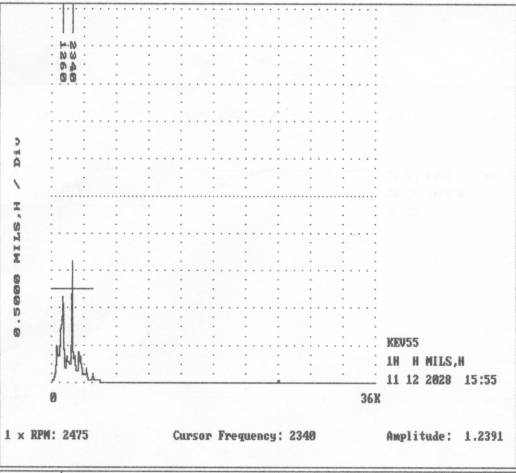
Figure 1: Pinion bearing and spacer forces.
As shown in figure 1, from the time of assembly, there are both tensile and compressive forces acting in this system. When the pinion nut is tightened on the end of the shaft, it induces a compressive force on the spacer between the inner and outer pinion bearings. (This spacer is also known as a “crush collar” or a “collapsible” spacer.) The purpose of this is to put the pinion in tension to keep the preload on the pinion bearings, that is, to keep the pinion “tight”.
Figure 2 shows an extremely simplified version of gear forces while in use. Note that the system can rotate two ways. During acceleration, the pinion drives the ring gear, which in turn drives the wheels. When decelerating, the ring gear drives the pinion. Each individual gear on both the ring and the pinion has a concave and convex side, (or a “coast” and a “drive” side) and when accelerating, the concave side of the pinion contacts the convex side of the ring. When decelerating, the convex side of the pinion contacts the concave side of the ring gear. The hypoid design of the gears produces forces in all three directions, vertically, laterally and longitudinally. The directions of these forces depend on whether the vehicle is accelerating or decelerating. The vertical loads are present due to the torque required to rotate the system, the lateral loads come from the tapered shape of the hypoid gears, and the longitudinal loads are induced by the “screw” action of the gears. When in motion, depending on the drive mode (acceleration versus deceleration), there is a force trying to push the pinion either toward or away from the ring gear, just like a screw driver forcing a screw into or out of a piece of wood.
Figure 2: Gear forces when in motion.
The collapsible spacer is designed to accept a certain amount of strain. It can be thought of as a spring between the pinion bearings, which keeps the pinion in tension. One idea was that the collapsible spacer actually yields under use because of the longitudinal force produced by the “screw” action of the ring gear and pinion. Repeated acceleration, especially rapid acceleration, was thought to fatigue the spacer and hence, loosen the pinion. Another idea was that the two surfaces of the spacer that contact the bearings were not parallel, thus inducing an unbalanced force on the spacer. Therefore, although the total load accepted by the spacer was below the load at yield, the uneven force distribution stressed one side more than the other. To test these theories, samples of collapsible spacers were made from different materials to increase strength. Additional samples were made using a grinding technique to ensure parallelism between the ends. Strain data was obtained using strain gages mounted on both prototype collapsible spacers and original spacers, but the results did not support the hypothesis.
Other methods were tested to reduce the whine noise, but none produced favorable results. For instance, an axle was covered in an insulating material to reduce the noise, one axle was filled with gear lubricant to try to muffle the noise and various drive shaft dampers were tested in the hope of damping the vibration. Many different specific solutions were offered, but most fell into two general categories; 1) try to muffle the noise (it would still be there, just not audible to the driver) and 2) stop the pinion from vibrating. The actual root cause of the vibration was never determined.
The student group began their project with knowledge of what had been tried and what did not work. Experience at the test track had also given them insight into specific situations in which the whine would occur, and it was this knowledge that allowed them to develop their theory about the source of the whine. First and probably most importantly, the whine always occurred at a very narrow range of speeds, usually around 55-60 MPH. Secondly, it only occurred during light acceleration or deceleration, and during cruising, when there was very little torque in the ring gear/pinion system.
While reading the course textbook, one student came across a passage that mentioned that when a noise (or whine) occurs in a gear system only at a certain speed (or multiples of a certain speed) the cause is usually resonance.1 This was the first clue that resonance may be the problem. The key to resonance is a consistent periodic driving force (at a natural frequency or critical speed), and the force was definitely present in the ring gear/pinion system. By analyzing the gear force diagrams, the group also realized that in high torque driving situations the pinion and ring gear would be pressed together very tightly, and the teeth would effectively be in constant mesh. Therefore, in these situations, vibration of the pinion would be minimal. In addition, resonance would be very unlikely because the force is constant, not periodic. The fact that the whine occurred during low torque situations supported the resonance theory. The group determined that in order to be convinced that resonance was the root cause, three things must match; 1) the gear mesh frequency, 2) the frequency of the audible whine, and 3) the natural frequency of the pinion gear.
The students began their investigation by measuring the vibration at the axle on an elevated stationary vehicle for baseline data. They anticipated elevated vibration at frequencies corresponding to the drive shaft’s RPM, the gear mesh, and perhaps the axle shaft RPM. They planned to introduce a heavier weight gear oil to reduce the amplitude of the related noise. Their baseline displacement data revealed elevated vibration primarily at the drive shaft RPM, as shown in figure 3. As a result of this finding, the oil weight change solution was dropped.
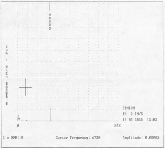
Figure 3: Baseline horizontal displacement data at the axle.
Consideration of the actual whining noise was the next logical step. The students recorded the interior noise under normal driving conditions while cruising at 55-60 MPH, then played the recording back through spectrum analyzer demonstration software. The software used was downloaded from the PAS-USA website.2 In addition to substantial wind noise, a constant peak was observed at approximately 447 Hz (26,820 CPM). Suspecting this to be the whining noise, the students next simultaneously listened to the recording and matched the noise to the tone produced by a frequency generator. The frequency was confirmed to be near 450 Hz, the gear mesh frequency at 55 MPH. This conclusion is indicated by the frequency spectrum and time waveform shown in figure 4.
Figure 4: Time waveform and frequency matching the 55 MPH whine.
Recognizing that speed-sensitive noise and vibration often means a resonance exists, the students decided to perform a bump test on the pinion, a simplified impact test.3 The pinion was the most likely source of the problem and therefore, it was necessary to find its natural frequency(ies).1 They removed the axle assembly’s cover plate to provide access to the pinion and measured its response. Unfortunately, conclusive data could not be obtained while the pinion was in the axle assembly. Testing the pinion by itself was necessary. Rather than disassemble one student’s vehicle, the group located an identical pinion at a junkyard for the second bump test. As figure 5 shows, the natural frequency was at 26,880 CPM (448 Hz). Pinion resonance generated the whining noise for the sample vehicle and pinion gear tested.
The students proposed two conceptual solutions for elimination of the whining noise: 1) change the pinion’s natural frequency or, 2) change the gear ratio to shift the gear mesh frequency above the range corresponding to normal driving. Both solutions require substantial redesign of the drive system of a vehicle that has been on the market for several years, at a cost that was believed to be prohibitive. The axle manufacturer proposed noise reduction as a potentially feasible means of separating the vehicle occupants from the gear whine. The automotive company subsequently awarded the axle contract to a competing supplier, in part due to the lack of resolution to the gear whine problem. The student group was not directly affiliated with the axle manufacturer or the automotive company, so they were not able to implement either of their proposed solutions. To the authors’ knowledge, the problem remains unresolved.
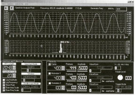
Figure 5: Bump test data for a same-model pinion.
[1] Wowk, Victor. (1991). Machinery vibration: measurement and analysis. McGraw-Hill, Incorporated, New York, 311.
[2] PAS-USA website, http://www.alloyscreens2000.com/pas/generator.html
[3] Eshleman, Ronald L. (1990). “Resonance and critical speed testing: part I, basic concepts and instrumentation. Vibrations, volume 6, number 3.