Kyle C. Quinnell
kquinnel@nmsu.edu
Department of Engineering Technology
New Mexico State University
This paper presents a way of using a PC computer as a an 8-bit Logic Analyzer. The technique uses the capabilities of the PC computer's parallel port to provide an 8-bit input. The software that provides the interface was written using Turbo C++. The software and hardware requirement for developing the Logic Analyzer are discussed in detail.
The purpose of this project was to create a useful yet easy to build Logic Analyzer that would provide much of the functionality of a real Logic Analyzer. The biggest drawback that the computer has is its sampling rate. The program was written on a 75 MHz Pentium computer which provided accurate sampling rates up to 10 kHz. Although this doesn't match the speed of real Logic Analyzers, this should be sufficient speed to be useful for many projects.
The only requirements for the computer are a VGA display and a parallel port. There is no speed requirement for the computer but of course the higher the clock rate of the computer the higher the obtainable sampling rate will be. Also, if you are using Windows 95, the program must be run in DOS mode.
As mentioned above, the parallel port is used to provide the interface for an 8-bit input. The reason the parallel port was chosen was because virtually all PC compatible computers have at least one.
The base address for the parallel port(s) can be found by looking at memory location 0000:0408 (hexadecimal). This can be done by using the DEBUG program which is provided with DOS. The following shows how this can be done.
Run the program from the DOS prompt
C:\debug

Type in the following command
-D0000:0408

The following data gets displayed on the screen
0000:0400                          78 03 00 00 00 00 00 00           x.......
0000:0410  63 D4 00 80 02 80 00 20-00 00 20 00 20 00 0D 1C   c...... .. . ...
0000:0420  65 12 62 30 75 16 67 22-0D 1C 64 20 30 0B 30 0B   e.b0u.g"..d 0.0.
0000:0430  30 0B 30 0B 3A 27 30 0B-34 05 30 0B 38 09 00 00   0.0.:'0.4.0.8...
0000:0440  00 00 C0 00 00 00 00 00-00 03 50 00 00 10 00 00   ..........P.....
0000:0450  00 0C 00 00 00 00 00 00-00 00 00 00 00 00 00 00   ................
0000:0460  0E 0D 00 D4 03 29 30 03-00 00 C0 04 AA B6 0B 00   .....)0.........
0000:0470  00 00 00 00 00 01 00 00-14 14 14 3C 01 01 01 01   ...........<....
0000:0480  1E 00 3E 00 18 10 00 60                           ..>....`
-
The first 2 byte number at address 0000:0408 corresponds to the base address of LPT1. The second 2 byte number corresponds to LPT2, and so on. The base address for LPT1 in this case turns out to be 0x378.
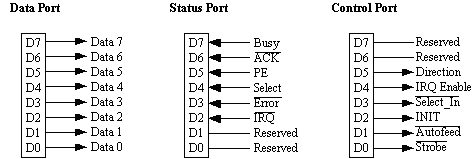
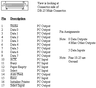
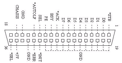
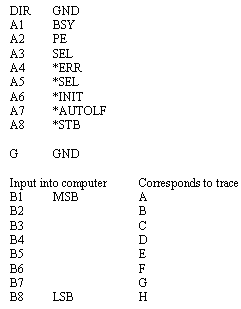
The parallel port is divided up into three 8-bit ports. The base address corresponds to the Data port. This port can be used to provide an 8-bit output. The address base+1 corresponds to the Status port. The address base+2 corresponds to the Control Port. By combining the Status and Control Port along with some minor bit manipulation it's possible to obtain an 8-bit input from the parallel port. The following diagrams show the layout of each of the ports and the pin description of the DB25 connector on the back of the computer.
The sampling rate is controlled by the 8253 or equivalent frequency divider that is built in to the computer. The input frequency to the 8253 is approximately 1.19Mhz. The 8253 has 3 frequency dividers/timers. Timer 0 is used to provide an 18Hz timing signal used for timing purposes. Timer 1 is used to provide the signal for the memory refresh. Timer 2 is used to control the internal speaker and other devices. Timer 0 is connected to IRQ0 of the 8259 PIC which in turn calls INT 08, which in turn calls INT 1c. Normally, the computer uses interrupt 08 to keep track of the time. By reprogramming the 8253 timer and writing a new INT 1c it is possible to control the sampling rate.
The code used to program the 8253 timer follows:
void set_rate(void)
{
	int number;
	int ratehi;
	int ratelo;

	number=65536/(sample_rate/18.2);
	ratehi=number&0xff00;
	ratehi=ratehi/256;
	ratelo=number&0x00ff;

	outportb(0x43,0x36);
	outportb(0x40,ratelo);
	outportb(0x40,ratehi);
}
First INT 1c is rewritten to sample the port and plot each of the 8-bits on the screen. Next, the 8253 timer is reprogrammed to "tick" at the desired sampling rate. When these two things have been done, INT 1c is called for each tick of the 8253. The frequency of the 8253 can be set anywhere from 18 Hz to approximately 65 kHz. However, the program limits the sampling rate from 100 Hz to 10 kHz.
The new interrupt 1c used in the program follows:
// New interrupt 0x1c
void interrupt sample()
{
	static int x=35;
	int y;
	int offset=0;
	char temp;
	int mask=1;                             // Start with LSB at top of screen

	ticks++;                                // Keep track of ticks
	if (sample_on) {

		if(index==0)
			x=35;

		if(x==639) {                    // Reset X coordinate
			x=35;
			cleartraces();
		}
		temp=readport();

		if (compare(stop_trigger_mask)==1)
			sample_on=0;

		for(y=429;y>=79;y-=50) {
			if (((int)temp&mask)>0)
				offset=25;
			else
				offset=0;

			mask=mask<<1;
			writedot(x,y-offset);
		}
			data[index%100000]=temp;
			index++;

		x++;

	}
}
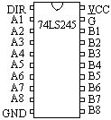
All that is required to build the interface is an ordinary printer cable and a 74LS245 buffer to provide protection for the port. Below are the necessary diagrams to build the interface.
V. Using the Program
The first screen shown will be the main menu. Below is a picture of the main menu.
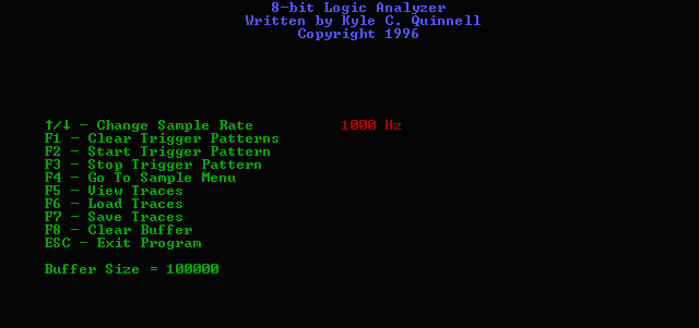
Features include:
Start Trigger Pattern: An 8-bit number that will start the sampling when it is encountered by the computer.
Stop Trigger Pattern: An 8-bit number that will stop the sampling when it is encountered by the computer.
NOTE: For both of the above options all 8 digits of the number must be entered. Valid characters are 1,0, or X.
Clear Trigger Patterns: Clears the Start and Stop Trigger patterns.
Sample Rate: Sample rate can be adjusted from 100 Hz to 10 kHz using the up and down arrow keys.
Go To Sample Menu: Takes you to the menu where the actual sampling takes place.
View Sample Traces: Takes you to the View Traces Screen
Load and Save Trace: Allows you to Load or Save the sampled data to a disk file.
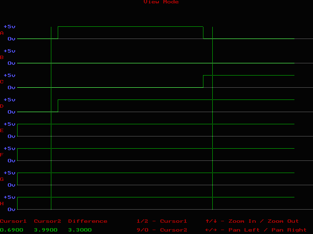
Clear Buffer: Clears all sampled data that is in buffer. Below is a picture of the View Traces Screen.
Features Include:
Cursor1 & Cursor2: Can be used to measure time or change in time.
Zoom In & Zoom Out: Used to change magnification of traces.
Pan Left & Pan Right: Used to scroll the traces left and right.
Another nice feature used in the program is the keyboard repeat rate is sped up to its maximum rate to improve the cursor speed on the View Traces screen.
The code used to speed up the repeat rate follows:
// Set keyboard repeat rate
void setrepeatrate(char x)
{
	asm {mov ah,3
	     mov al,5
	     mov bh,0
	     mov bl,x
	     int 0x16
	}
}
To download the executable file along with the C source code click here
Brey, Barry B. The Intel Microprocessors 8086/8088, 80186, 80286, 80386, 80486. Macmillan Publishing Company.
Johnson, Jeffrey Hirst. Build Your Own Low-Cost Data Acquisition and Display Devices. TAB Books, 1994.
Bergsman, Paul. Controlling the World with your PC. HighText, 1994.
Anderson, Peter H. http://et.nmsu.edu/~etti/fall96/computer/printer/printer.html