A DEVELOPMENT OF AN INTERFACE DESIGN ALTERNATIVE
| Ahmed Elsawy, Ph.D. Mech. Eng. | Veekit O’Charoen, M.S. Mfg. Eng. | |
| elsaw@uni.edu | ocharo58@iscssun.uni.edu | |
| Professor | Doctoral Degree Candidate | |
| Department of Industrial Technology | Department of Industrial Technology | |
| University of Northern Iowa | University of Northern Iowa |
Abstract
In designing pneumatic circuit, a real challenge is to enable designers to visualize the circuit during the design stage and answer what if? questions. The objective of this preliminary study was to develop an interface design alternative (icon , pull-down, and screen menus) for pneumatic circuit's design. It was also an attempt to determine the possibility of using it as a tool to help designers associate the menu systems with commands, and visualize circuit design improvements. This study pr ovides three main benefits. Firstly, each of the menus helps designers to associate these pictures with commands and to visualize circuit design improvement. Second, the ability to preview pneumatic circuits and minimize rejected designs. Last, is the ability to create more prototypes in less time and at lower cost.
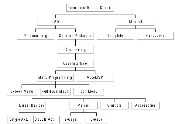
AutoCAD is a general-purpose drafting system designed with an open architecture. It can be customized and its many features can be extended. As a result, users can expand and shape AutoCAD according to their need [2]. P revious research has been accomplished by Promis-E (ECT -International, Brookfield, Wisconsin) for an electrical design package that customizes AutoCAD to the needs of electrical control designer's [3]. In this paper, it was assumed that the menu system is developed for the group of designers who have knowledge of AutoCAD’s (R13) user interface and pneumatic design circuit. This study was limited to two-dimensional pneumatic schematics. Furthermore, the symbols emphasize the function and methods of oper ation of components. These symbols are fully explained in the ANSI/Y14.17, ANSI/Y32.10 [4,5]. The AutoCAD’s user interface (icon, screen, and pull down menus) are preconfigured by Autodesk [6]. To develop and analyze the user interface for pneumatic circuit designs, type-of-hierarchy diagrams are used to illustrate the task and subtask of the menu systems (see Fig 1).
Icon menus are user-customizable screens that popup over AutoCAD’s graphic screen when called from a menu macro. Icon menus are made up of AutoCAD slide files. Icon menu screens have up to 20 slide files per screen as well as an associated list box c ontaining the names of the slides or other text. Slides can be generated by using the command LINE, TEXT, ARC and CIRCLE for some symbols. The use of the COPY, MIRROR AND ARRAY Polar commands may be helpful as well. Slide files are special files that co ntain images in a different format from the drawing file. This format permits slide files to be displayed much more efficiently by entering the MSLIDE command and designating a file name to store the slide. It is also necessary to generate the text file in order to collect slide files from the previous step. A Program called SLIDELIB is available as an AutoCAD utility. It can be used to compile slide files into slide libraries. Then in the next step, a straight ASCII text editor can be used to prepar e a file that contains list of names, which refer to existing slide files. The Icon menus use AutoCAD slide files that contain image abbreviations and can be drawn quickly to display menus. It is necessary to specify the icon menus section by using the section label ***ICON. Figure 2 shows an experimental program that is written with menu programming by using text editor.
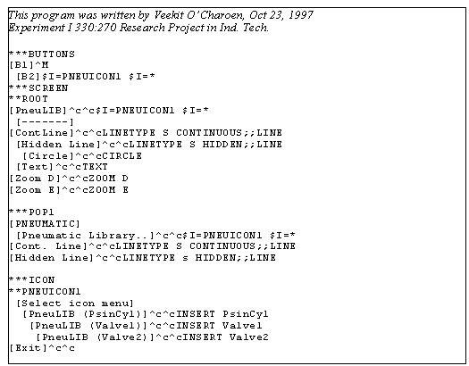
Figure 2. The example of icon menu programming.
The screen menu is on the right side of AutoCAD’s graphic screen. Unless users purposely configure AutoCAD without a screen menu area, this menu area is present whenever users are editing a drawing. The screen menu area contains either the standard AutoCAD menu (which comes with the program) or another menu that users have loaded. The screen menu section of a menu programming always begin with the line ***SCREEN. Each line that follows may contain a command or a series of commands (macros), which users execute simply by picking the item from the screen menu.
Pull-down menus are an extension of the standard AutoCAD menu structure. Pull-down menus are specially implemented AutoCAD menus that popup to overlay a portion of the user display. Highlighting a menu-bar item and pressing the pick button causes the associated pull-down menu to be displayed. Pull-down menus are devices in the menu file. Like other devices, the ***POP labels identify the defaults. The following figure shows one of the pull-down menus after menu programming was implemented (Fig 3).
Figure 3. Pull-down menu from this study
The user interfaces fall into three categories: icon, pull-down, and screen menus. Icon menus consist of five different pages: cylinders, valves, controls, accessories, and pipes. Each of the pages contains 20 items which is the maximum that t he icon menu can show at any one time. Pull-down menus contain a total of seven categories as cascading (or hierarchical) menus. The way of selecting information is by moving the graphics cursor to the assist pull-down menus and clicking. Some of the m enu items have the arrow symbol, to indicate that the menu item cascades to reveal more macros as a submenu. Screen menus contain six items. Each of the items can be paged as users select one item from the main page selection. As a result, a new screen menu will appear as a sub-screen menu. The following picture is the menu system, which was developed in this study (Fig 4).
Figure 4. Menu system for pneumatic design circuits
Conclusion and Recommendations
A menu driven interactive graphic software package has been developed to help pneumatic designers to visualize the circuit during the design state. Each menu has a different program patterns but can be enclosed in one system in which programs work si multaneously with each other. For example, drawing (valves, cylinders, lines etc.) can be extracted from the icon menus. The use of icons allows the user to select from a set of defined options, rather than specification memory. This development provides three main benefits. Firstly, each of the menus helps designers to associate these pictures with commands and visualize circuit design improvement. Second is the ability to preview pneumatic circuits and minimize rejected designs. Last, is the ability to create more prototypes in less time and at lower cost. This investigation is a step toward the development of comput er aided design system for pneumatic design circuit.
It is recommended for future research those studies of tasks that are more complex and different interface types, such as animation programming and color-enhanced icons are explored. The addition of animation to the circuit may possibly provide a link to the AutoLISP language programming and slide/script files.
References
[1] Hensel, F., "How can fluid power software help productivity? (Computers and Software in Fluid Power: Software Showcases) (Editorial)" Hydraulics & Pneumatics, Volume 50, Issue 2 (1997) pp.4.
[2] Autodesk, Inc., "AutoCAD Customization Guide" (1994).
[3] Larson, K., "Schematic software jump start design work", Control Engineering,, Volume 44 (1997), pp. 56-57.
[4] American National Standard Institute. Y14.17: Fluid Power Diagrams[5] American National Standard Institute. Y32.10: Graphical Symbols for Fluid Power Diagrams.
[6] Grabowski, R., "The AutoCAD: Programming and Customizing Quick Reference - R13", (1997) New York: Autodesk Press.