Kamil Vrba and Josef Čajka
Department of Telecommunications
Brno University of Technology
Purkyňova 118, 612 00 Brno
Czech Republic
ABSTRACT
A general four-port second-kind current conveyor (GCC) is defined. The network operating in the voltage-mode as a universal second-order filter (UF) is presented. The design procedure of a UF with the aid of GCCs is described. The conversion of the derived UF to its adjoining counterpart is shown.
INTRODUCTION
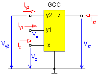
For the RC-active network design a general four-port current conveyor (see Fig. 1) was introduced. Any current conveyor has three port types. Current, voltage, and output ports are designated as x, y, and z respectively. The current conveyor in Fig. 1 has one current port, x . One independent current is being considered (let it be denoted as I*). The conveyor being considered has two voltage ports, y (therefore the notation second-kind) and one output port, z.

Fig.1. Four-port second-kind current conveyor schematic
The independent current I* will always be conveyed to the output port with either positive or negative sign whereas the conveyance coefficients to the voltage ports are +1, -1 or 0 . Replacing the conveyance coefficients with letter symbols produces a general current conveyor characterized by the following relations:
![]()
![]()
![]()
![]()
![]() (1)
(1)
Here
(a1 , a2
, c)
![]() (+1,
-1) and
(b1 , b2)
(+1,
-1) and
(b1 , b2) ![]() (0,
+1, -1). If
b1 = b2 = 0, it is considered a zero class conveyor. If the
current I* is
conveyed to only one voltage port, it is considered a class one conveyor,
if it is conveyed to both voltage ports, it is considered a class two conveyor.
(0,
+1, -1). If
b1 = b2 = 0, it is considered a zero class conveyor. If the
current I* is
conveyed to only one voltage port, it is considered a class one conveyor,
if it is conveyed to both voltage ports, it is considered a class two conveyor.
The following procedure is based on the presumption that a universal second-order RC filter operating in the voltage mode is being designed. The term universal filter is used to denote a network that can be used as a lowpass, bandpass or highpass filter but also as a notch filter or an allpass filter.
The design procedure follows:
First choose a suitable autonomous circuit that must contain a minimum of four passive one-ports (because of the second order). Choose as an active elements two general four-port current conveyors of the second kind (because of the voltage mode operation) as in Fig. 1. A simple autonomous circuit that contains the elements chosen is shown in Fig. 2, where all the passive elements are grounded.
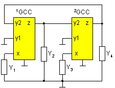
Fig. 2. Chosen general autonomous circuit
As the next step, calculate the characteristic equation (CE) of the chosen autonomous circuit. For the circuit in Fig. 2 we can obtain by routine calculation:
![]() (2)
(2)
The second digit in the conveyance coefficient refers to the serial number of the current conveyor. Characteristic equation (2) can be simplified by choosing
b22 = 0 (3)
Then obtaining
![]() (4)
(4)
For the grounded terminals y1 of both GCCs (see Fig. 2) it will also hold, in addition to (3), that
![]() (5)
(5)
For the network under consideration to be stable, further conditions must be fulfilled
![]() and
and
![]() (6)
(6)
Choosing Y1 = G1, Y2 = sC1, Y3 = G2, and Y4 = sC2, from (4) the characteristic polynomial (it will appear in the denominator of voltage transfer) in the canonic form is obtained.
![]() (7)
(7)
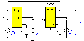
Fig. 3. Selected prototype of proposed universal filter
Knowing that the characteristic polynomial in (7) will not change to an arbitrary branch connect an ideal voltage source [1]. While respecting relations (3) and (5) calculate all voltage transfers from the existing sources connected in grounded branches to potential output ports with a grounded common terminal. From the results obtained select the prototype shown in Fig.3.
Using a computer it is easy to calculate the output voltage of the four-port in Fig. 3. It is:
![]() (8)
(8)
For the network in Fig. 3 to operate as a universal filter it must, with a view to the conditions in (6), hold that
![]() and
and
![]() (9)
(9)
All conditions in (3), (5), (6) and (9) can be rewritten as follows:
![]() ,
, ![]() ,
,
![]() ,
,
![]() ,
,
![]() (10)
(10)
There are eight possible ways to fulfill conditions (10). All the possible cases have been tabulated below. The network, according to variant C, is shown in Fig. 4. The first current conveyor is of class one, the second conveyor of class zero.
Replacing the first conveyor of class one in Fig.4 by an equivalent current conveyor of class zero generates the four-port in Fig. 5. The current that was initially conveyed from the terminal x to the terminal y has been conveyed to the additional output terminal z+ [2] so that no current is flowing to the voltage ports of the conveyor itself (the conveyor is then of class zero) [3].
|
variant |
a11 a21 b11 b21 c1 |
a12 a22 b12 b22 c2 |
network |
|
A |
+1 +1 0 1 1 |
+1 1 0 0 1 |
|
|
B |
+1 +1 0 1 1 |
1 +1 0 0 +1 |
|
|
C |
+1 1 0 +1 1 |
+1 1 0 0 +1 |
Fig. 4 |
|
D |
+1 1 0 +1 1 |
1 +1 0 0 1 |
|
|
E |
1 +1 0 1 +1 |
+1 1 0 0 +1 |
|
|
F |
1 +1 0 1 +1 |
1 +1 0 0 1 |
|
|
G |
1 1 0 +1 +1 |
+1 1 0 0 1 |
|
|
H |
1 1 0 +1 +1 |
1 +1 0 0 +1 |
|
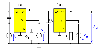
Fig. 4. Universal filter according to variant C
The network in Fig. 5 can be realized by either using the differential-voltage second-generation current conveyor DVCC [4] or by using the universal current conveyor UCC [5]. The realization with the aid of the UCC device is shown in Fig. 6.
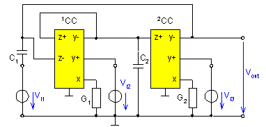
Fig. 5. Universal filter according to variant C realized with universal UCC current conveyors
Then for all four-ports with conveyors according to the above table the output voltage is given by the relation
![]() (11)
(11)
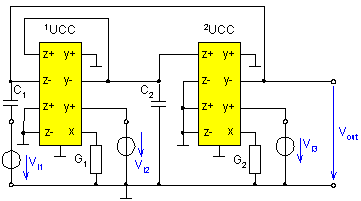
Fig. 6. Universal filter realized with UCC devices
If Vin = Vi2 = 0 (the respective ports are short-circuited), the network in Fig. 6 works as a lowpass filter. If, however, Vi1 = Vi3 = 0, we obtain an inverting second-order bandpass filter. For the network in Fig. 5 to operate as a highpass filter there must, according to (11), then: Vi3 = 0 and Vin = Vi1 = Vi2 and also C1 = C2 (this is provided for already in the filter design).
The notch filter is obtained in such a way that in the network in Fig. 6 an existing voltage is applied to all input ports ( Vin = Vi1 = Vi2 = Vi3) and C1 = C2. The network in Fig. 6 will operate in the voltage mode as an allpass filter if it holds that:
![]() a
a ![]() .
.
Voltage-mode to current-mode conversion and vice versa
For any first-order current conveyor of class zero there exists an adjoining current conveyor of class zero with the same number of ports [3]. Converting any conveyor above does not change the terminal x. The voltage terminals y must be interchanged with the output terminals z. Simultaneously it is necessary to change the conveyance coefficient (non-inverting Ϋ inverting). This can be written as follows: y+Ϋz and y Ϋ z+. The symbol Ϋ denotes mutual interchange.
The current transfer functions of the network considered are as follows:
![]() ,
(13)
,
(13)
![]() ,
(14)
,
(14)
![]() .
(15)
.
(15)
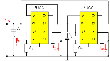
Fig. 7. Universal biquad filter operating in the current mode
Conclusion
This paper has described the procedure used in designing a second-order filter (biquad) using a general four-port current conveyor. The above procedure can also be applied to the design of any active RC network by means of another type of general current conveyor [6].
Acknowledgment
This work has been supported by the Grant Agency of the Czech Republic (Grant No. 102/00/1037).
References
[1] BIOLEK, D., VRBA, K., ČAJKA, J., DOSTΑL, T.: General three-port current conveyor: a useful tool for network design. Journal of Electrical Engineering, 2000, Vol. 51, No. 1-2, pp. 36-39.
[2] VRBA, K., ČAJKA, J., LATTENBERG, I.: Design of novel RC-active four-port networks with universal current conveyors. Proc. of Int. Conf. Radioelktronika 2000, STU Bratislava, 2000, pp. I1 I4.
[3] ČAJKA, J. DOSTΑL, T., VRBA, K.: General view on current conveyors and their application in network design (to be published)
[4] ELWAN, H. O., SOLIMAN, A. M.: Novel CMOS differential-voltage current conveyor and its application. IEE Proc.-Circuits Devices Syst., 1997,Vol. 144, No. 3, pp. 195-200.
[5] BEČVΑŘ, D., VRBA, K.: Novel generations of inverting current conveyor using Universal Current Conveyor. Electronic Journal Technology Interface, 2000, Vol. 3, No. 4, web.bsu.edu/tti
[6] VRBA, K., ČAJKA, J.: Filter and oscillator design using general current conveyors. Electronic Journal www.ElectronicsLetters.com, 2000, no. #1,11, 2000.