|
|
Volume 3 No.3 Fall 1999 |
ISSN# 1523-9926 |
|
|
Volume 3 No.3 Fall 1999 |
ISSN# 1523-9926 |
William
E. Cole
wcole@coe.neu.edu
School of Engineering Technology
Northeastern University
ABSTRACT
New advanced computer aided design (CAD) tools are now available that allow students not only to draw objects in the computer, but also to determine forces, stresses, and motion. Students can even fabricate objects directly from the computer model using rapid prototyping tools. These tools can also be used to teach fundamental engineering material. Thus, a curriculum can be envisioned where freshman learn how to create solid models within the CAD environment. Throughout the rest of the curriculum, advanced analysis tools can be used to help teach and reinforce course material including design, strength of materials, and mechanics. These three threads represent over 25% of the curriculum in mechanical engineering technology at Northeastern University. This paper discusses how these tools could be integrated into the curriculum.
INTRODUCTION
Engineering material is taught today the same way it has been for decades using lectures, homework assignments, and laboratory experiments, all based upon using mathematical models to represent physical phenomena. This may, however, not be the best way to teach. Many education studies have shown that students retain only a small fraction of what they hear or read. The retention rate increases dramatically when a student says or does--when there is hands on learning (Ekwall, 1978). This is especially true with technology students who learn best through observing and doing. Hence the extensive use of laboratories in the engineering technology program.
New tools are needed to improve our teaching. Technology students are hands-on graphic learners. Their learning improves when they can see things and work with them. Hence graphics can provide us this additional teaching tool. Graphics is the primary method of communications within the engineering profession. Engineers draw new ideas as sketches to focus concepts in their mind and show them to others. After preliminary work, details are added to these sketches and they are formalized into drawings. These drawings are continually revised as analyses are performed and tests conducted to improve the design and create the final product. Historically, the actual drawing of a product was performed independently from the analysis. The advent of the computer has changed this design process. It is now possible to construct the initial sketch as a three dimensional solid model in the computer. Design analyses can then be performed directly on this solid model to determine its properties and reaction to applied loads. Thus, the steps of drawing have been closely linked to the analysis. Analysis by sophisticated tools on a computer model has replaced analysis by hand with simplified geometry for many applications (Waterman, 1997; McIlvaine, 1997).
This trend has generated many acronyms for the processes involved: computer-aided design (CAD), computer-aided design drafting (CADD), computer-integrated manufacturing (CIM), or concurrent engineering. These acronyms all refer to the close integration of drafting, analysis, and manufacturing into the design process. These concepts incorporate:
Although these tools have been developed to help engineers do their job better, they have not been used to teach engineering and engineering technology.
Engineering technology curriculums typically include graphics in the freshman year. As recommended by Crittenden (1996), these "freshman-level courses . . . develop three-dimensional visualization skills and to understand the conventions used on engineering drawings." Specific topics included in these courses include producing two-dimensional drawings of three-dimensional objects, drawing conventions, and sketching. Students are also taught computer graphics skills on a CAD package. Unfortunately, many curriculums do not force the students to use these skills until their senior design course, years later. In its report, "Making Quality Count in Undergraduate Education," the Education Commission of the States cited a number of attributes of a quality undergraduate experience (AAHU, 1996). One of those attributes is the "ongoing practice of learned skills." In other words, "use it or lose it." The report stated that if opportunities to use basic skills are not continually provided, those skills in many students quickly "atrophy." Thus, for an undergraduate in a four-year program of study, many skills learned in the freshman year will essentially be forgotten or seriously diminished by graduation unless those skills are applied in upper level courses.
Use of advanced CAD analysis programs to help teach upper level material will help overcome the barrier of fragmented learning in the development and reinforcement of skills among engineering technology students. The incoming freshman can be taught how to build three dimensional computer models. This tool can then be used throughout the curriculum to teach the basic technical principles that the students need in their professional career. These skills include visualization of objects, design, strength of materials, and motion analysis. In essence, the entire mechanical engineering technology curriculum can be refocused around the graphics analysis tools initially introduced in the Freshman year, as shown in Figure 1.
Figure 1: Teaching Engineering Analysis from the Geometric Model
This approach creates an interesting analogy to the engineering curriculum at the beginning of this century. Engineering curriculums in the early part of this century had a strong graphical thread throughout the four years. Graphics was taught in the freshman year. Graphical analysis tools were then used to teach many of the upper level courses. Particular subjects that were taught graphically included mechanisms, mechanics, machine design, and steam turbines. There was even a course in graphical analysis included in the 1926 Northeastern University curriculum [NU, 1926]. Thus using graphical analysis tools will allow us to return to the curricular approach used successfully in the past while still including modern analytical analysis techniques.
COMPUTER ANALYSIS TOOLS IN THE TECHNOLOGY CURRICULUM
This vision is to use computer analysis tools to improve teaching. This requires a curriculum that teaches the basic building blocks in the freshman year and then builds upon this base in the upper level courses. The basic building block is solid modeling, which would be taught in the introductory graphics course. Then in the upper level courses, advanced analysis capabilities can be used to help teach basic course material. This analysis capability will not replace traditional mathematical tools that teach the basic understanding of the subject matter. Rather they can supplement these tools to demonstrate the concepts visually and allow more varied and complex problems to be addressed within the technical courses. Thus a unified curriculum, with extensive use of reinforced learning, will result where students progressively learn based on the foundations provided by the lower level courses and repetitively used in the upper level courses.
This program will build on the freshman graphics course. The basic building block is the solid model. Under this vision, tools for rapid prototyping, property analysis, finite element analysis, and kinetic analysis of the solid model will all be available. These tools for analysis can then be used in the basic engineering technology courses to enhance the learning of the course material. This will use the basic design and analysis tools the student knows and understands to help teach new material--the basic principle of reinforced learning. The next few sections give a brief introduction to each of these tools, how they can be used to improve student learning, and where they impact the typical mechanical engineering technology curriculum.
Finite Element Analysis
Finite element analysis (FEA) is incorporated in few engineering technology programs (Roth, 1995). This is because the complexity of FEA forces most courses to focus on the theoretical aspects of generating FEA models rather than application of this analysis tool to solve real world problems. FEA techniques are now becoming less daunting and can now be introduced into engineering technology programs. For example, in mechanical engineering many schools "are implementing numerical methods of designing mechanical and or structural components within junior or senior-level courses" (Rastani, 1996). Thus, students can be introduced to this tool which is becoming increasingly common in the workplace. There are still problems, however, in introducing FEA techniques into a traditional mechanics of materials course. These problems include how to use this difficult software with very specific data entry requirements (Dally, 1994). At the University of California, this was overcome for engineering students by devoting six hours of class time and "substantial" student efforts outside the classroom (Lieu, 1993). In another case, a graphical front end was created for a FEA program to overcome these difficulties at the expense of generalization capability of the software (Dally, 1994).
Instructors have successfully introduced FEA analysis into the mechanics of materials course. At the University of California, FEA "enhances the conceptual understanding of structural loading and their effects on the stresses of irregularly shaped objects. . . . [this] allows students to synthesize geometrically complex parts without an overriding concern or burden of analytical complexity. Student surveys indicate that this aspect of the course is perceived to be fun, challenging, and extremely worthwhile." (Lieu, 1993).
Solid modeling overcomes this difficulty of complex software with very specific data entry requirements. Once the solid model is created, there are several programs available that can generate the mesh patterns and perform the FEA analysis on the model transparently. Thus FEA can be introduced quickly and easily into the mechanics of materials course. This approach has been used in engineering at the Northern Arizona University (Howell, 1993). Using a combination of Cosmos Designer and AutoCad, they reported very favorable results in a freshman design/graphics course.
This solid modeling approach to FEA was used at Northeastern University in a solid modeling course. Design Space from ANSYS was used for the FEA. This program appears as a menu item within AutoCad. Once the solid model is created, the student selects the object, adds loads and supports, and then Design Space calculates the stresses. The program is automatic and can be explained in a one hour class. A module was developed in the solid modeling course to teach finite element analysis. Within a two hour lecture, students were introduced to FEA and how to use Design Space. The students were then given a homework assignment to do with a partner. An example student assignment is shown in Figure 2 where the colors on this figure represent the stress on the object when loaded in tension with 5000 pounds.
This is ideal for students in either strength of materials or heat transfer courses. In the introductory graphics course, the students are taught solid modeling. In the upper level course, the student will learn how to perform finite element analysis on this solid model. This can then be used to teach the student how stresses and forces are distributed within an object and how to design an object to maintain these stresses at acceptable levels. Thus, in a strength of materials problem, the student can create the solid model, set up the FEA program, and do the analysis. This analysis can show local stresses and be used either as an assignment to determine the stresses or as a design project to maintain stresses below a critical value. In either case, this allows the student to use this valuable tool to learn about stresses and forces within an object.
Figure 2: FEA Analysis of a Stress Concentration Problem
Kinematics and Kinetics
Engineering students have difficulty understanding the complex concepts in kinematics and kinetics. Part of this problem is that the required vector analysis is highly mathematical and engineering technology students have trouble with these mathematical concepts. A second problem is that mechanics is the study of motion, but textbooks and chalkboards, the traditional classroom teaching tools, cannot show motion (Flori, 1996). However, a computer can show motion. In a study at the University of Missouri-Rolla, a multimedia simulation program was introduced in the dynamics class. Students found the program improved visualization, learning of dynamics, and made the course more enjoyable (Flori, 1996).
Advanced modeling tools, such as Working Model, now work within AutoCad to provide motion analysis of solid models. These advanced modeling tools allow the objects to be modeled both in geometry, rotational points, and forces. The programs can show the resulting motion of the object, thus visualizing the motion. This can be done either individually by the students or demonstrated to the class by the instructor. Additionally, forces involved are calculated automatically. This capability has been used successfully in a number of universities (Grammoll, 1994; Iannelli, 1994). Thus, the students can use the very same graphic tools that they used in freshman graphics to analyze and visualize motion.
Rapid Prototyping
Rapid prototyping is a concept that has received widespread attention recently. With rapid prototyping the solid model can be physically fabricated directly -- no intervention by a skilled prototype builder is necessary. A good overview of the many processes and available equipment is presented by Barr (1995).
The original rapid prototyping process uses a laser system to solidify plastic resin in successive layers. This process is not appropriate for use in undergraduate classes because the models are expensive and they take too long to build (about six hours). This point was demonstrated by the experience of the GMI Engineering and Management Institute where eight hours of time on the rapid prototyping machine are budgeted for each student (Sullivan, 1996). Thus, for a class of 100 students, a project that each student completes in a couple of weeks is not feasible.
New low cost machines are now available that can create the physical model directly from the computer solid model. One of these system, the JP-5 system from Schroff Development Corporation, replaces the printer on a personal computer with a cutter. This cutter creates paper outlines for successive layers of the model that the student then be presses together to create the object. This system is shown in Figure 3.
Figure 3: JP-5 Rapid Prototyping System
One of these rapid prototyping systems was used at Northeastern University in a solid modeling Class. Example student generated models are shown in Figure 3. This rapid prototyping system allowed the students to actually build the object they drew and hold it in their hand. With this system, it is feasible to give a project to a large number of students.
A third approach low cost approach to rapid prototyping, is to use numerically controlled machining (Schmidt, 1997). This approach has been largely overlooked in the literature. This is because the capability to machine objects directly from the solid model has only recently been developed. This capability allows students to create solid models in the computer and then use a translator program to generate the tool paths. They can then take this code to the model shop, load it into the CNC machine, and have their object machined. By machining in wax, plastic, or aluminum, machining time should be very short—a matter of minutes.
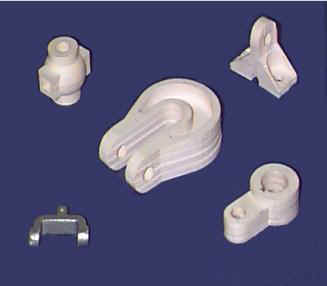
Figure 4: Models Created by Students on the JP-5 System
CONCLUSIONS
Using computer aided analysis tools to teach basic engineering material should improve student learning. These tools should help the students learn, improve their ability to use their knowledge, and make learning more enjoyable. This should result in improved achievement by the students, improved retention in school, and improved careers after graduation. Specifically, using computer aided analysis tools to teach should:
ACKNOWLEDGEMENT
This work was initiated at an Undergraduate Faculty Enhancement (UFE) workshop supported by the National Science Foundation (NSF), Grant No. DUE-9455076, through the Division of Undergraduate Education (DUE), Directorate for Education and Human Resources (EHR).
REFERENCES
AAHU, Making Quality Count in Undergraduate Education, American Association of Higher Education, 1996.
Barr, Ronald, et al, "Extending Engineering Design Graphics Laboratories to have a CAD/CAM Component Part III: Prototype Manufacturing," Proceedings of the 50th EDGD Midyear Meeting, Ames, Iowa, 1995, p83.
Crittenden, John Barrett, "Requirements for Successful Completion of a Freshman-Level Course in Engineering Design Graphics", Engineering Design Graphics Journal, Winter 1996, p5.
Dally, James W. et al., "Experiences in Introducing Finite Elements in Mechanics of Materials," Proceedings 1994 ASEE Annual Conference, 1994, p385.
Ekwall, Eldon, Diagnosis and Remediation of the Disabled Reader, Allyn and Bacon, 1978.
Flori, Ralph E., Koen, Mary A., and Oglesby, David B., "Basic Engineering Software for Teaching (BEST) Dynamics," Journal of Engineering Education, January 1996, p61.
Gramoll, K., "Using Working Model to Introduce Design to a Freshman Engineering Course," Proceeding of the ASEE 1994 Annual Meeting, Edmonton, Alberta, Canada, June 26-29, 1994.
Howell, Steven K., "Finite Element Analysis in a Freshman Graphics Course," Engineering Design Graphics Journal, Winter 1993, p29.
Iannelli, J., "Mechanics in Action: On the Development of Interactive Computer Laboratories for Engaging Engineering Mechanics Education," Proceeding of the TBEED 1994 Annual Conference, Gatlinburg, Tn, November 18-19, 1994.
Lieu, D. K. and Talbot, N. H., "Introducing Graphical Finite-Element Structural Analysis to an Undergraduate Curriculum," Engineering Design Graphics Journal, Winter 1993, P33.
McIlvaine, Bill, "CAD Makes A Difference in Time to Market," Managing Automation, May 1997, p18.
NU, Northeastern University Bulletin, Northeastern University, 1926.
Rastani, Mansur, "Integration of Manufacturing Design Applications in FE-Based Applied Mechanics Courses," Proceeding 1996 ASEE Annual Conference, Session 3268.
Roth, David E, and Johnson, David H., "Finite Element Analysis in Engineering Technology", Journal of Engineering Technology, Fall 1995, p8.
Schmidt, Joseph, "CNC Machining Keeps Pace with new Technologies," Automotive Engineering, July 1997, p97.
Sullivan, Laura L., and Erevelles, Winston F., "Integration of Polymer Processing, Computer Integrated Manufacturing, and Metal Casting Processes via Rapid Prototyping", ASEE Annual Conference Proceedings, 1996.
Waterman, Pamela, "In Search of FEA and CFD," Design Engineering, October 1997, p40.